Iranian Classification Society Rules

< Previous | Contents | Next >
Section 17 Flexible Hose Assembly
1701. Application
1. The requirements of this Section apply to tests and inspection for the approval of flexible hose as- sembly of metallic or non-metallic materials in accordance with the requirements in Pt 5, Ch 6,
102. 5 (2) of the Rules.
2. The requirements of this Section apply to the flexible hose assembly used in oil fuel, lubricating hydraulic and thermal oil systems, fresh water and sea water cooling systems, compressed air sys- tems, bilge and ballast systems, and Class III steam systems in accordance with Pt 5, Annex 5-9 of the Guidances and may also apply to the flexible hose assembly intended for other uses except for high pressure fuel oil injection systems and fixed extinguishing systems.
1702. Data to be submitted
The following reference data are to be submitted to the Society in addition to those specified in
102.
(1) Description of design and cross sectional drawings, manufacturer's specification mentioned na- tional or international standard.
(2) Specification of the materials(inner tube, outer tube, couplings etc. mentioned national or interna- tional standard).
(3) Welding or brazing procedure specification(only for metallic hose assembly).
(4) Mounting procedure of the couplings to the hoses.
(5) Design pressure(or maximum working pressure).
(6) Temperature range.
(7) Type of medium to be covered.
(8) Special operational limitations.
(9) Marking of the hose assembly.
(10) A detailed information, in case where the flexible hose or fitted coupling is made by different manufacturers.
1703. Type tests
1. Flexible hose assembly of non-metallic materials
(1) Test specimen
At least three hose assemblies which are of the same type but different in their nominal diame- ters, i.e. the smallest, middle and largest size, are to be subject to the tests for each type. In case where the flexible hose assemblies do not pass all or any part of the tests in the follow- ing table, two assemblies of the same size and type that failed are to be retested and if even one of the assemblies fails the second test, then that size and type of the assembly is to be considered unacceptable.
(2) Test condition
The temperature of a test room is to be maintained at 20 ~ 30℃ and it is to be recorded in
the test report. The test is to be carried out with test specimen which is left for more than 24
hours after vulcanized and subsequently in the test room maintaining the standard temperature
more than one hour before test.
(3) Test items, test method and criteria
The requirements in Table 3.17.1 are, in principle, to be considered as the criteria for the type tests of flexible hose assembly of non-metallic materials. For application of the tables, see be-
low:
(a) Those asterisk in the column of criteria represent the items where acceptance criteria do not apply. These data are for reference only and the results are to be recorded in the test
reports.
(b) A test method other than those given in Table 3.17.1 may be employed by this Society if deemed appropriate of its equivalency.
Guidance for Approval of Manufacturing Process and Type Approval, Etc. 2015 109
![]()
Table 3.17.1 Testing methods and Criteria of flexible hose assembly of non-metallic materials
Test Item | Test Method | Criteria | |
Measurement of Dimension | |||
Inner Diameter | Two end points of inner side of hoses are to be measured at the right angle direction and make average. | The diameter is to be within allowable tolerance. | |
Outer Diameter | Outer side of hoses is to be measured at the right angle direction and make average. | ||
Thickness | Measure the thinnest point. | ||
Performance Test | |||
Pressure Test | Pressure Test | One side of the specimen is free, Test medium : water or oil, Test pressure : a pressure 1.5 times of the design pressure, Test duration : 5 minutes. | During test period, no rupturing, leaking are permitted. |
Burst Test | Test pressure : a pressure 4 times of the design pressure, Test duration : 5 minutes | ||
Leakage Test | One side of the specimen is free, Test medium : inert gas or air, Test pressure : a pressure same as the design pressure, Test duration : im- merse the specimen in water for 5 minutes. | ||
Vacuum Test | One side of the specimen is free, Test pressure : absolute pressure 88 KPa, Test duration : 5 minutes. | ||
Cold Test | This test is applied to the hose assembly which the design temperature is 0℃ and below. Remain the specimen in low temp. room at minimum design temp. for 5 min. and bend both sides within 12 seconds as re- quired bending radius as Fig below and then examine the condition of the specimen. Remain the tested specimen at room temp. and it is to be subjected to pressure test at least 1.5 times of design pressure.
| During test period, no rupturing, leaking are permitted. | |
Electric Test | Electric Conduction Test | Connect 4.5 V battery and 3.8 V, 0.3 A light on the specimen and ex- amine the electric conductivity in accordance with the result of lighting. In case where metal is attached on hose, carry out the test between metal of both ends and otherwise, between electric wires of both ends. where there are not the electric wires, carry out the test after connecting metals to both ends. | The light is to be turned on. |
In su la t io n Resistance Test | The specimen is to be installed in accordance with Fig below and measure insulation resistance using 500 V insulation resistance tester af- ter connecting metals to both ends.
| The measured in- sulation resistance shall not be more than 1MΩ. | |
Adhesion Test | Adhesion test of each layer of hose is to be carried out in accordance with KS M 6787. | * | |
110 Guidance for Approval of Manufacturing Process and Type Approval, Etc. 2015
![]()
![]()
Table 3.17.1 Testing methods and Criteria of flexible hose assembly of non-metallic materials
Test Item | Test Method | Criteria | |
Ozone Resistance Test | This test is to be carried out in accordance with KS M 6790 using hose which is rolled on a cylinder and examine crack of outer rubber layer. | * | |
Thermal Aging Test | After aging the specimen in accordance with KS M 6788 during re- quired time, leave it for 3 hours ~ 24 hours at room temp. Bend it un- til 180° within 5 seconds in accordance with Fig below and then exam- ine the condition of it. The test specimen is to be subjected to pressure test at least 1.5 times of design pressure.
| * During test period, no rupturing, leaking are permitted. | |
Impulse Test | Hose Without Flexing | The specimen where the nominal bore size up to 22 mm is to be bent through 180° and the nominal bore size above 22 mm is to be bent through 90°. Repeat maximum impulse pressure which is 133 % of de- sign pressure until 4× 10⁵ or breakdown and record the number of cycle. The detailed test procedure is prescribed in KS M ISO 6803.
| During test period, no rupturing, leaking are permitted. Leakage at the end fitting, blow-off or rupture of the hose within 25 mm of the fitting is to be considered as failures. |
Hose With Flexing | After installing a revolving manifold and a horizontally reciprocating manifold, carry out the test in accordance with the test cycle of Fig The detailed test procedure is prescribed in KS M ISO 6802. | ||
Mechanical Test of Vulcanized Rubber | |||
Tensile Test | Tensile test is to be carried out in accordance with KS M 6782 and measure tensile strength and elongation. | * | |
Hardness Test | Hardness test is to be carried out in accordance with spring type test method of KS M 6784. | * | |
Aging Test | Aging Test (Air Heat) | Carry out this test in accordance with air heat aging test method of KS M 6788 and calculate the variation of tensile strength and elongation before and after this test. In this case, test temp. is one of among 70± 1℃, 100± 1℃ and 120± 1℃ and test time is one of among 48 hours, 72 hours and 96 hours. | * |
Aging Test (Steam Heat) | After air heat aging test, the same specimen is to be left in saturated vapour during the required time and then left for 24 hours. Carry out tensile test and calculate the variation of tensile strength and elongation. | * | |
Dipping Test | Dipping test is to be carried out in accordance with KS M 6789 and calculate the variation of volume, tensile strength and elongation before and after this test and examine the condition of the surface. | * | |
Guidance for Approval of Manufacturing Process and Type Approval, Etc. 2015 111
![]()
![]()
Minimum width of burner (mm) | Outside diameter of hose (mm) |
50 | up to 25 |
100 | over 25 up to 75 |
150 | over 75 up to 125 |
200 | over 125 up to 150 |
250 | over 150 up to 200 |
Table 3.17.1 Testing methods and Criteria of flexible hose assembly of non-metallic materials
Test Item | Test Method | Criteria |
Fire Resistance Test | ||
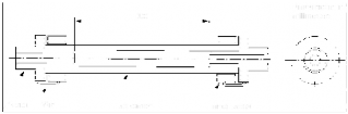
Fire Resistance Test | ① Hose length : Minimum 500 mm and above. ② Test medium : Water only. ③ Installation of test specimen : The test specimens are to be installed on the test bench such that the burner end extends beyond a hose sitting by at lease 20 mm such that the fitting is completely en- closed by the flames. ④ Width of burner : In order to ensure that the flames reliably enclose the test specimen, the minimum burner widths shown in Table be- low is to be observed. Table Width of burner ⑤ Preparation : The test specimen is to be rinsed with the test medium water for at least 1 minute, in order to evacuate as far as possible the air contained in the test specimen. ⑥ Measured values and Measuring points: The following measured val- ues is to be determined at the measuring points indicated in Fig a) Water temp. at measuring points 1 and 2 b) Flame temp. at measuring points 3 and 4 c) Flow rate of water d) Pressure inside test specimen during the flame application
⑦ Test temperature : The test duration starts at the moment the test specimen is exposed to the test temperature which is to have been reached at both measuring points in accordance with Table below. ⑧ Pressure : 5± 0.2 bar during flame application ⑨ Duration of test : 30 minutes, the duration starts at the moment the test specimen is exposed to the test temp. which is to have been reached at both measuring points. ⑩ Pressure test : Following the flame application, a pressure test is to be carried out at a pressure twice of the design pressure for 2 minutes. | The test specimen remains tight during the proof pressure test after flame application. |
Temp. | of water at temp. measuring point 1 | 80±2℃ | |
Temp. | of water at temp. measuring point 2 | max. 85℃ | |
Temp. and 4 | of flame at temp. measuring points during test | 3 | 800±50℃ |
112 Guidance for Approval of Manufacturing Process and Type Approval, Etc. 2015
![]()
![]()
2. Flexible Hose Assembly of Metallic Materials
(1) Test specimen
At least three hose assemblies which are of the same type but different in their nominal diame- ters, i.e. the smallest, middle and largest size, are to be subject to the tests for each type. In case where the flexible hose assemblies do not pass all or any part of the tests in the follow- ing table, two assemblies of the same size and type that failed are to be retested and if even one of the assemblies fails the second test, then that size and type of the assembly is to be considered unacceptable. In case where nominal diameters are not various, a test specimen which may be selected at random from the production line or stock is subject to be tested.
(2) Test condition
Test room is to be maintained at 20 ~ 30℃ and the temperature of the test room is to be re-
corded in the test report. The test is to be carried out with test specimen which is left for
more than one hour in the standards temperature before test.